The control board of the Cluster Box uses a program called nodectl to handle out of band management for the nodes. This includes things like powering nodes on and off, and providing serial console access. It is (very) specific to this hardware, and unfortunately not open source. In this post, I will detail how I reverse engineered the binary and rewrote it in Go, fixing some bugs along the way.
Unexpected problems
I had originally planned on this post being about the first boot and setup of the box. Unfortunately, I hit several major issues and may need to RMA the control board. I’m in talks with the manufacturer about the issue, but I don’t have a resolution yet. I’ll complete and upload a setup post at a later date.
What is out of band management (OOBM)?
Out of band management is typically a way to remotely access devices as if you were physically at the device, using it directly. They often include features like powering devices on and off, allowing console access, and monitoring hardware-level metrics. This is usually done over a network via HTTP (via web GUI or Redfish API), or SSH. Out of band management is extremely useful for debugging and fixing low level issues when an operating system is not remotely available. It’s a standard feature on enterprise hardware, and is typically implemented via an “baseboard management controller” (BMC). This baseboard management controller is usually a separate computer contained in the hardware’s chassis, often integrated into the motherboard.
The Cluster Box implements this for all four Blades as a part of the control board. As discussed in the last post, the control board contains a MT7620A processor. This processor runs OpenWRT and acts as a PCIe root complex for the PCIe switch (more on this in a future post). It is also used essentially as a “power button” for the Blades, which can only be started via software running on this board. The user interface for this is a custom userspace program called nodectl, which calls a couple of Linux kernel APIs via sysfs to control the node’s power state.
I’d like to implement a Kubernetes cluster autoscaler for this hardware at some point, and the first step is understanding how OOBM for the box (and therefore nodectl) works.
nodectl functionality
Before diving into the binary’s logic, it’s really helpful to have an idea of what the binary does. To start, I ran nodectl with no arguments to see what subcommands are available:
mixtile@MixtileClusterBox:~$ nodectl
Usage: nodectl commands:
   nodectl list
   nodectl poweron (--all|-n N)
   nodectl reboot (--all|-n N)
   nodectl flash (--all|-n N) -f /path/firmware.img
   nodectl console -n N
   nodectl rescan
I then ran each command with various arguments. The output of these will be useful later on in determining what parts of the binary’s assembly are associated with each command.
mixtile@MixtileClusterBox:~$ nodectl list
If no device is found, run the rescan command and then the list command to view the device.
03:00.0 Network controller: Mixtile Limited Blade 3 (rev 01)
04:00.0 Network controller: Mixtile Limited Blade 3 (rev 01)
05:00.0 Network controller: Mixtile Limited Blade 3 (rev 01)
06:00.0 Network controller: Mixtile Limited Blade 3 (rev 01)
mixtile@MixtileClusterBox:~$ nodectl poweron --all
mixtile@MixtileClusterBox:~$ nodectl poweron -n 1
mixtile@MixtileClusterBox:~$ nodectl reboot --all
mixtile@MixtileClusterBox:~$ nodectl reboot -n 1
mixtile@MixtileClusterBox:~$ nodectl flash
The function is under active development, please stay tuned.
mixtile@MixtileClusterBox:~$ nodectl rescan
mixtile@MixtileClusterBox:~$ nodectl console -n 1
picocom v3.1

port is        : /dev/ttyCH343USB1
flowcontrol    : none
baudrate is    : 1500000
parity is      : none
databits are   : 8
stopbits are   : 1
escape is      : C-a
local echo is  : no
noinit is      : no
noreset is     : no
hangup is      : no
nolock is      : no
send_cmd is    : sz -vv
receive_cmd is : rz -vv -E
imap is        :
omap is        :
emap is        : crcrlf,delbs,
logfile is     : none
initstring     : none
exit_after is  : not set
exit is        : no

Type [C-a] [C-h] to see available commands
Terminal ready

root@blade3:~# hostname
blade3
root@blade3:~# <I entered the C-a C-x picocom exit sequence here>
Terminating...
Thanks for using picocom
This provides several useful pieces of information:
- The
nodectl listcommand provides a unique-looking string (“If no device […]”) as a part of the output. - Most of the
nodectl listcommand output lines are formatted the same aslspci. - Almost none of the commands provide any output at all.
- The
consolesubcommand uses picocom for serial access.
Binary information
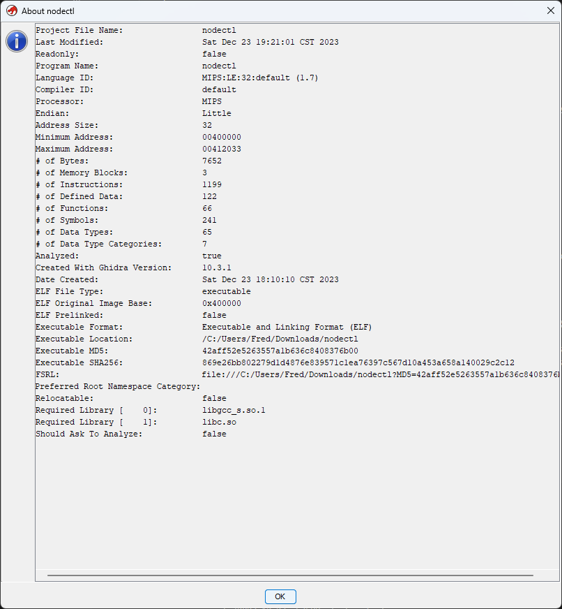
There’s one last thing I’d like to check before actually disassembling the binary. There are several pieces of metadata that will be useful during analysis, and later while rewriting it - the file metadata.
First up is the size of the executable code. There is a (loose) correlation between this and how difficult it’ll be to reverse engineer. Using readelf on a local copy of the binary, I can see the size of each section:
me@local:/tmp $ readelf --program-headers nodectl
readelf: Warning: Section 0 has an out of range sh_link value of 4195984

Elf file type is EXEC (Executable file)
Entry point 0x400690
There are 9 program headers, starting at offset 52

Program Headers:
  Type           Offset   VirtAddr   PhysAddr   FileSiz MemSiz  Flg Align
  PHDR           0x000034 0x00400034 0x00400034 0x00120 0x00120 R   0x4
  INTERP         0x000154 0x00400154 0x00400154 0x0001c 0x0001c R   0x1
      [Requesting program interpreter: /lib/ld-musl-mipsel-sf.so.1]
  ABIFLAGS       0x000170 0x00400170 0x00400170 0x00018 0x00018 R   0x8
  REGINFO        0x000188 0x00400188 0x00400188 0x00018 0x00018 R   0x4
  LOAD           0x000000 0x00400000 0x00400000 0x01c70 0x01c70 R E 0x10000
  LOAD           0x001c70 0x00411c70 0x00411c70 0x00118 0x00140 RW  0x10000
  DYNAMIC        0x0001a0 0x004001a0 0x004001a0 0x00120 0x00120 R   0x4
readelf: Error: no .dynamic section in the dynamic segment
  GNU_STACK      0x000000 0x00000000 0x00000000 0x00000 0x00000 RW  0x10
  NULL           0x000000 0x00000000 0x00000000 0x00000 0x00000     0x4
“Program headers” are used to setup the program for execution when loading the binary into memory. This blog post what happens when a program is executed in more detail. The important part to pick out are headers with the E flag set. These headers refer to sections that contain executable code. The above output shows that the only executable section is 0x01c70 bytes long, or roughly 7 KB. 7000+ bytes sounds like a lot, but this section also contains some read-only data that makes up a significant portion of the size.
Another important piece of information that this shows is that there is a DYNAMIC header. This means that the program is dynamically linked, and may depend on other libraries. The INTERP section shows that a dynamic linker should be used to load the file (musl in this case, rather than the GNU libc linker that most Linux systems use).
The libraries that the binary depends on can be viewed by reading the DYNAMIC section and filtering it down to the NEEDED type:
me@local:/tmp $ readelf --dynamic nodectl | grep NEEDED
readelf: Warning: Section 0 has an out of range sh_link value of 4195984
readelf: Error: no .dynamic section in the dynamic segment
 0x00000001 (NEEDED)                     Shared library: [libgcc_s.so.1]
 0x00000001 (NEEDED)                     Shared library: [libc.so]
Fortunately it looks like only libc and libgcc_s are required. Most dynamically-linked program compiled by GCC will depend on these.
The last thing to check is the binary’s file header:
me@local:/tmp $ readelf --file-header nodectl
ELF Header:
  Magic:   7f 45 4c 46 01 01 01 00 01 00 00 00 00 00 00 00
  Class:                             ELF32
  Data:                              2's complement, little endian
  Version:                           1 (current)
  OS/ABI:                            UNIX - System V
  ABI Version:                       1
  Type:                              EXEC (Executable file)
  Machine:                           MIPS R3000
  Version:                           0x1
  Entry point address:               0x400690
  Start of program headers:          52 (bytes into file)
  Start of section headers:          0 (bytes into file)
  Flags:                             0x70001005, noreorder, cpic, o32, mips32r2
  Size of this header:               52 (bytes)
  Size of program headers:           32 (bytes)
  Number of program headers:         9
  Size of section headers:           40 (bytes)
  Number of section headers:         0 (1)
  Section header string table index: 0
Here are the important takeaways from this output:
- The binary is for a 32 bit MIPS ISA.
- The binary is in little endian format.
This is mostly relevant for compiling a replacement later.
Disassembly
Armed with this information about the binary, I am now ready to start analyzing the program logic. There’s a lot of ways to do this. Because the binary is (presumably) very simple, I am going to statically analyze it by reading through the assembly and partially-decompiled. Ghidra is a series of tools that can make this somewhat easy. A full tutorial on how to use Ghidra is out of scope of this post.
I start by loading the assembly into Ghidra and opening it. While doing so, I also import libc.so and libgcc_s.so.1, which should help with analysis. The tool correctly reads and displays most of the binary information listed above.
Opening the binary for the first time also prompts for auto analysis. This provides a bunch of useful, human-readable information about the disassembly and greatly reduces the effort required to understand the program flow. The default options are usually fine.
The Symbol Tree provides shows a list of functions that the auto analysis tool found. The main window shows the file’s contents, as well as the instructions or data that each byte corresponds to as appropriate. The panel on the right shows a best attempt at decompiling the currently selected function to C. Note that this is nowhere near perfect, and produces nearly-incomprehensible code in many cases.
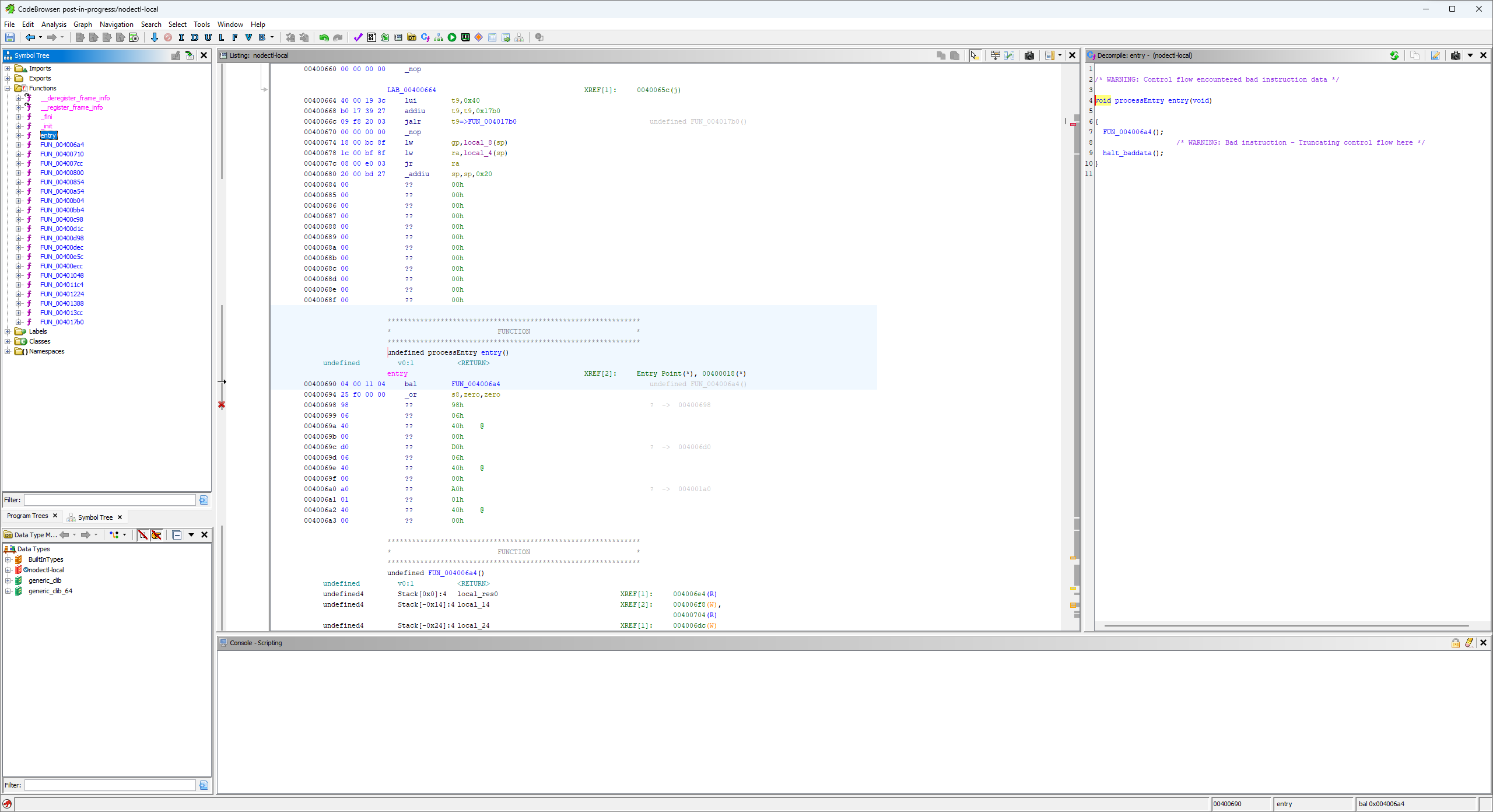
There were only 25 functions found, and many of them are for setting up what is essentially a C runtime. These functions handle things like initializing data structures. On bare metal (not the case here), there is usually some instructions to setup in-memory data structures like the stack and heap as well. This series provides a great writeup on how this works.
Starting with the exported entry function, I follow the logic to the real main() function of the program:
This is the compiled version of the int main(int argc, char *argv[]) source code function, and should have the same signature. However, as shown in the “decompiled” pane, it does not. The auto analysis tools are very smart, but they do not recognize all the types. Additionally, the binary does not have symbol information for the functions, so there is no information on it’s actual source code name. It can only be assumed to have the above signature because I know the requirements that the compiler puts on this function, based on where it is in the call stack.
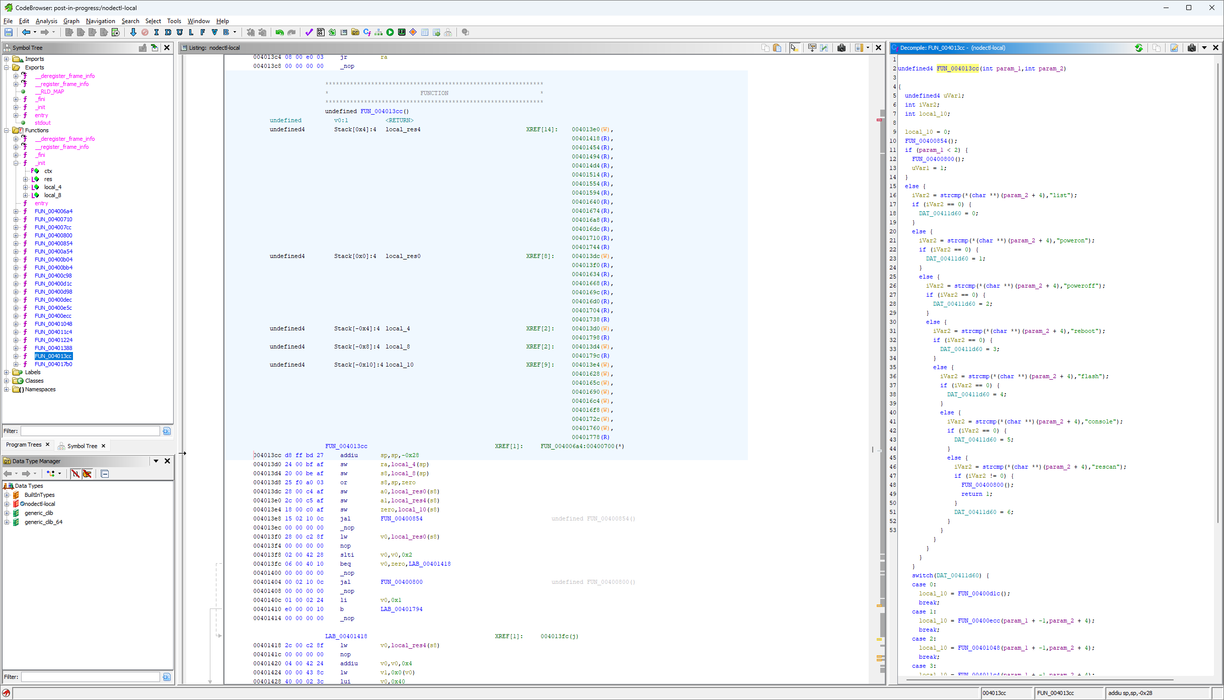
Fortunately Ghidra provides some useful tools to rename functions and variables, and to change their types. This makes the analysis easier:
I’ve also renamed the local variables, based off of what I think they do. While I’m making progress, the full logic of this function still isn’t clear. I need to determine what the remaining FUN_* functions do to fully understand the control flow. The FUN_00400800 function looks like this1:
void FUN_00400800(void)
{
  fputs("
    Usage: nodectl commands:\n
        nodectl list\n
        nodectl poweron (--all|-n N)\n
        nodectl reboot (--all|-n N)\n
        nodectl flash (--all|-n N) -f /path/firmware.img\n
        nodectl console -n N\n
        nodectl rescan\n
    \n
  ",stdout);
  return;
}
This is easily recognizable as the output of the first test in the nodectl functionality section. This is clearly a CLI “usage” function. I rename the function and continue on to the rest. I’m not going to list out each one for brevity’s sake. There are, however, a few interesting ones that I’ll cover.
Nested loops and unknown types
There is one function that is significantly more complex than the rest:
int FUN_00400854(void)
{
  undefined *puVar1;
  undefined *puVar2;
  undefined4 uVar3;
  FILE *file_handle;
  int local_58;
  int local_54;
  char string_buffer [56];

  for (local_54 = 0; local_54 < 4; local_54 = local_54 + 1) {
    puVar1 = (&PTR_DAT_00411d30)[local_54];
    puVar2 = (&PTR_DAT_00411d50)[local_54];
    for (local_58 = 0; local_58 < *(int *)(&DAT_00411d40 + local_54 * 4); local_58 = local_58 + 1) {
      uVar3 = *(undefined4 *)(puVar1 + local_58 * 4);
      snprintf(string_buffer,0x32,"/sys/class/gpio/gpio%d",uVar3);
      file_handle = fopen(string_buffer,"r");
      if (file_handle == (FILE *)0x0) {
        file_handle = fopen("/sys/class/gpio/export","w");
        fprintf(file_handle,"%d\n",uVar3);
        fclose(file_handle);
        snprintf(string_buffer,0x32,"/sys/class/gpio/gpio%d/direction",uVar3);
        file_handle = fopen(string_buffer,"w");
        fprintf(file_handle,"%s\n",puVar2);
        fclose(file_handle);
      }
    }
  }
  return 0;
}
This function contains several variables of unknown types, a couple of loops, and some read-only data structures. It looks like this is accessing the sysfs GPIO interface. This can give some clue as to what each variable is. There are a couple of snprintf that have a formatted string that contains /sys/class/gpio/gpio%d. The %d shows that uVar3 must be a number type, and the current undefined4 type shows that it must be four bytes long. On this platform (this is compiler/machine dependent) the type must be int or uint. The formatted string shows that this is the number of the pin in the GPIO interface, which cannot be negative. I’ll update this variable from undefined4 uvar3 to uint pin_number.
The actual type of the puVar2 variable can be similarly deduced. The last fprintf statement’s formatted string (%s\n) shows that puVar2 must point to a null-terminated character array, or string. The function call is writing to the gpio<pin_number>/direction file, so the variable must represent whether the pin is an input or an output. I’ll retype it as char * pin_direction.
Determining the type and usage of puVar2 helps determine the type and purpose of the read-only data stored at PTR_DAT_00411d50. Based on the way it’s accessed (pin_direction = (&PTR_DAT_00411d50)[local_54]), PTR_DAT_00411d50 must be an array of strings that determines what direction a given pin should be (char ** type). The values that this array points to are either out\0 or in\0\0, which confirms this. I’ve renamed the array from the vague PTR_DAT_00411d50 to a more informative PIN_DIRECTIONS. Continuing to work backwards, the same PIN_DIRECTIONS array access indicates that local_54 is really a pin counter. This, and the for loop that iterates it shows that there must be four pins for each local_58 variable.
The remaining two variables undefined * puVar1 and int local_58 are a little harder to comprehend. The local_58 var is another counter of some kind, as shown in the nested for loop. This loop is ran through four times, once per pin index. The DAT_00411d40 + pin_index * 4 arithmetic indicates that DAT_00411d40 must be a data structure that has four bytes per entry, which corresponds to the type of the local_58 variable. I’m going to guess that this is defined as int DAT_00411d40[4]. The same logic can be applied to the puVar1 variable, and PTR_DAT_00411d30 data. It looks like the PTR_DAT_00411d30 data must be typed as uint PTR_DAT_00411d30[4][4]. Given that there are four Blades per enclosure, I am going to assume that PTR_DAT_00411d30 stores the GPIO pin number for a given pin_number/blade_number combination.
All the variable types and purposes have been identified. It looks like this function configures the GPIO pins that this program uses to talk with each Blade, by enabling userspace access (via the export file), and by setting the direction (via the direction file). Here’s the properly annotated function:
int setup_gpio_pins(void)
{
  uint *node_pin_numbers;
  char *pin_direction;
  uint pin_number;
  FILE *file_handle;
  int blade_number;
  int pin_index;
  char string_buffer [56];

  for (pin_index = 0; pin_index < 4; pin_index = pin_index + 1) {
    node_pin_numbers = (&PIN_NUMBERS)[pin_index];
    pin_direction = PIN_DIRECTIONS[pin_index];
    for (blade_number = 0; blade_number < INT_ARRAY_00411d40[pin_index];
        blade_number = blade_number + 1) {
      pin_number = node_pin_numbers[blade_number];
      snprintf(string_buffer, 0x32, "/sys/class/gpio/gpio%d",pin_number);
      file_handle = fopen(string_buffer, "r");
      if (file_handle == (FILE *)0x0) { // If NULL
        file_handle = fopen("/sys/class/gpio/export", "w");
        fprintf(file_handle, "%d\n", pin_number);
        fclose(file_handle);
        snprintf(string_buffer, 0x32, "/sys/class/gpio/gpio%d/direction", pin_number);
        file_handle = fopen(string_buffer, "w");
        fprintf(file_handle,"%s\n", pin_direction);
        fclose(file_handle);
      }
    }
  }
  return 0;
}
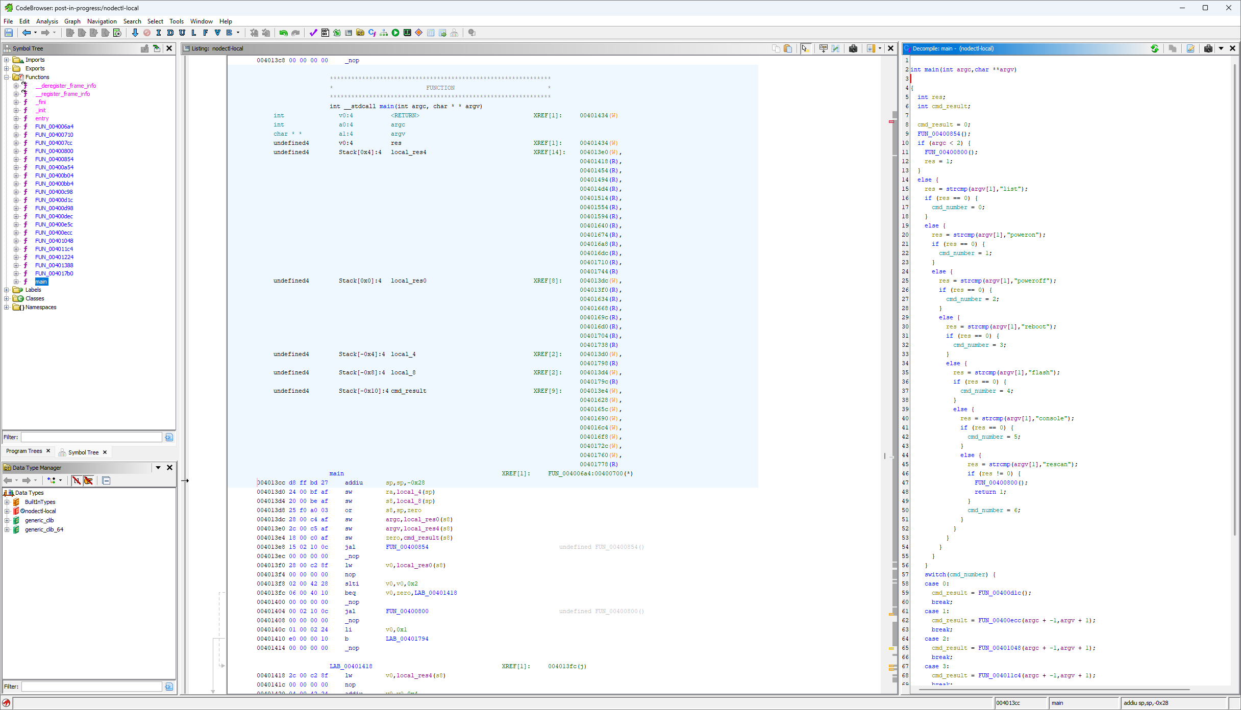
Getting back to the main point
With the setup_gpio_pins function annotated, the main function is much easier to understand. I’m not going to copy/paste it here for brevity’s sake. Here’s some pseudocode instead:
if a subcommand was not provided:
    print usage
    exit with code 1

switch on subcommand:
    <command>:
        call command function with provided subcommand args
        if non-zero return value
            print usage
            exit with code 1
    default:
        print usage

exit with code 0
This is the general process that I followed for the remaining ~20 functions. Here’s a few things that I noticed:
- The
listsubcommand does in fact calllspci | grep <PCIe addresses>. This reports nodes as online even when they are powered off, which may or may not be intentional. - There are three pins that are set high when turning a given node on. One is for the node’s LED. I assume that another is for the node’s board, and the last one is for the PCIe switch (but I have no easy way to verify).
- The
poweroffcommand is not listed in the usage, but still works. - The
powerofflogic only sets one pin low instead of three. I think this is a bug. - The
consolecall does a literalpicom -b 1500000 /dev/ttyCH343USB<serial port number for node>. - The
rescanfunction does a literalecho 1 > /sys/bus/pci/rescan.
Rewriting and testing
After getting a good understanding of the binary, I rewrote it in Go. This was pretty straightforward, however, I did have a couple of issues compiling for the target architecture. I found this article on compiling for MIPS, and the author even happened to be compiling for the same processor as me. This helped me solve a couple of issues, including one that I wasn’t expecting: binary size. The built binary is very large for what it does - 5.2MB:
vscode ➜ /workspaces/nodectl (master) $ du -h build/nodectl
5.2M    build/nodectl
This is about a third of the entire storage space of the control board. Fortunately, upx was able to shrink it significantly:
vscode ➜ /workspaces/nodectl (master) $ upx -9 build/nodectl
                       Ultimate Packer for eXecutables
                          Copyright (C) 1996 - 2020
UPX 3.96        Markus Oberhumer, Laszlo Molnar & John Reiser   Jan 23rd 2020

        File size         Ratio      Format      Name
   --------------------   ------   -----------   -----------
   5373952 ->   1832724   34.10%  linux/mipsel   nodectl

Packed 1 file.
vscode ➜ /workspaces/nodectl (master) $ du -h build/nodectl
1.8M    build/nodectl
While still massive (relatively speaking), it is now small enough to leave some free space behind.
I’ll probably package the binary as an OpenWRT opkg artifact at some point to make installation easier. For now, I can simply scp the file onto the control board. It seems to be working:
mixtile@MixtileClusterBox:~$ sudo /tmp/nodectl list
03:00.0 Network controller: Mixtile Limited Blade 3 (rev 01)
04:00.0 Network controller: Mixtile Limited Blade 3 (rev 01)
05:00.0 Network controller: Mixtile Limited Blade 3 (rev 01)
06:00.0 Network controller: Mixtile Limited Blade 3 (rev 01)
Wrapping up
I’ve covered how the Cluster Box facilitates remote management of the nodes, and rewrote it’s tooling in Go to enable future projects. The Go module needs some work in the long term, but I’m happy with what it can currently accomplish. In the next post I will probably either cover some more details on how the TCP/IP over PCIe network works, or I’ll cover what I had originally planned for this post (depending on where my conversations with the manufacturer go).
-
This is formatted slightly different from the actual value to be easier to read. ↩